Guide du Code, Partie 1 – 6

Souvent, les utilisateurs du Code se retrouvent dans des situations où certains règlements peuvent leur sembler étranges. Ces situations se présentent autant chez les concepteurs, les consultants, les installateurs, les inspecteurs, les étudiants, les formateurs que chez les experts qui développent les normes, et sont souvent liées au fait que le règlement a été mal identifié ou mal interprété. Il n’est peut-être pas celui requis par la tâche à effectuer. Le Code est un document complet et détaillé et la réponse ne se trouve pas toujours facilement. Voici un guide qui au cours des prochains mois vous aidera à trouver votre chemin dans le Code. Cette semaine, la Section 10–Mise à la terre et continuité des masses.
The CE Code is a comprehensive document. Sometimes it can seem quite daunting to quickly find the information you need. This series of articles provides a guide to help users find their way through this critical document. In this article: Section 10 — Grounding and bonding.
Section 10 — Grounding and bonding
Section 10 is a general section of the Code and applies to all installations unless amended by other Sections of the Code. It’s Scope outlines requirements for:
• grounding of electrical systems and service equipment
• bonding of non-current-carrying metal parts of equipment and conductor enclosures, together and to ground
• the use of ungrounded systems and neutral grounding devices
Special terminology used in this section and found throughout the code include bonding, bonding conductor, ground, ground fault, ground fault detection, ground fault protection, grounded, grounding, grounding conductor, grounding electrode, and grounding system.
These are all thoroughly defined in Section 0.In general terms, bonding refers to a low impedance permanent connection of all non-current-carrying metal parts together, and grounding refers to a permanent low impedance connection to the earth.
The stated object of Section 10 is to provide rules for
• bonding metal parts and systems together and to the grounded system conductor to reduce the danger of electric shock and property damage, providing a low impedance path for fault current back to the source, and establishing an equipotential plane to minimize potential difference between non-current carrying metal parts
• grounding the electrical system and bonding of non-current carrying metal parts to earth to minimize any potential difference to earth
• using an ungrounded system or a neutral grounding device in the system to provide alternates to a solidly grounded system, and minimizing any damage from a single fault by limiting the magnitude of the fault current.
System and circuit groundingrules 10-102 to 10-116 provide guidance on when and where, as well as exceptions to, grounding specific two-wire dc systems, three-wire DC systems, AC systems, electric arc furnaces, electric crane circuits, isolated circuits, circuits of less than 50V, and instrument transformer circuits.
Once you have determined your specific grounding needs, Grounding connections for systems and circuits rules10-200 to 10-212 provide specific detailed guidance on how to ground various systems. Appendix B also contains some helpful diagrams.
Conductor enclosure bondingrules 10-300 to 10-304 are guidelines for when and where to bond metal enclosures for service conductors, underground service conductors, as well as enclosures for other than service conductors.
Equipment bondingrules 10-400 to 10-414 provide the varying requirements for when and where to bond all metal non-current carrying parts of fixed equipment general, fixed equipment, specific, non-electrical equipment, portable equipment, instrument transformer cases, cases of instruments, meters, and relays-operating voltage 750v or less, cases of instruments, meters, and relays-operating voltage over 750V, as well as non-metallic wiring systems.
The Bonding methodsrules 10-600 to 10-626 will guide you through the steps needed to ensure an effective continuous, low-impedance bonding connection when Bonding service equipment, Metal armour or tape of service cable, Bonding at other than service equipment, Loosely jointed metal raceways, bonding jumpers, short sections of raceway, fixed equipment, portable equipment, pendant equipment, bonding equipment to the grounded system conductor (bonding to ground), and electrolytic-type water heaters. Helpful suggestions are also contained in the Appendix B notes.
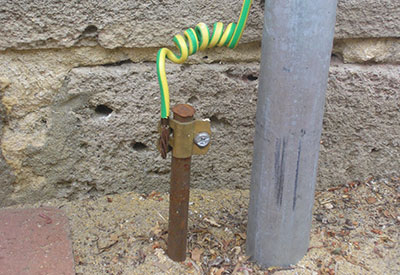
Rule 10-700Grounding electrodessets out the requirements for establishing a grounding connection through the use of electrodes.There are specific rules for various grounding electrodes including manufactured grounding electrodes (both rod electrodes and plate electrodes), field-assembled ground electrodes, and in-situ grounding electrodes forming part of the existing infrastructure. Rule 10-702 sets out spacing and interconnection requirements for grounding electrodes where more than one grounding electrode exists at the building including those electrodes used for signal circuits, radio, lightning protection, communication, community antenna distribution systems, and any other purpose. Rules 10-704 and 10-706 deal with railway track electrodes and the use of lightning rod system conductors and grounding electrodes.
Rules 10-800 to 10-820 are rules governing continuity, material selection, sizing, and installation of grounding and bonding conductors. The size of a grounding conductor is determined by the type of system, either AC or DC. Thesize of a bonding conductor as determined by Table 16A or 16B depends on the size of the associated circuit conductor (Table 16A) or on the size of the associated bus-bar (Table 16B).
Once you have installed the correct type and size of bonding and grounding conductor, pay close attention to the connection of these conductors as specified in rules10-900 to 10-906Grounding and bonding conductor connections. The continuity and safety of a low-impedance path to reduce the danger of electric shock and property damage, and providing a low impedance path for fault current back to the source, depends on adequate and sound connections.
The final two subjects of Section 10 deal with grounding and bonding of lightning arresters and the installation of neutral grounding devices.
Pour lire les articles précédents de la série:
– Guide du Code, Partie 1 – 10
William (Bill) Burr est l’ancien président du Canadian Advisory Council on Electrical Safety (CACES), et l’ancien directeur de l’Electrical and Elevator Safety pour la province de la Colombie-Britannique. Il a aussi été directeur de l’Electrical and Gas Standards Development et directeur du Conformity Assessment pour le Groupe CSA. Bill peut être rejoint à Burr and Associates Consulting au billburr@gmail.com.


