Utiliser les plus récentes technologies pour la formation des apprentis électriciens
L’industrie électrique a vu beaucoup de changements en peu de temps. L’utilisation généralisée des composants à semi-conducteurs et de logiciels a contribué à changer la façon dont nous intégrons les composants. Éclairage, commandes de moteur, CVCA, contrôle de la puissance, systèmes d’automatisation à petite échelle et systèmes de communications ont tous été révolutionnés par les commandes électroniques.
Je crois que l’exposition précoce à des contrôles à semi-conducteurs est essentielle pour l’apprenti électrique d’aujourd’hui. Lorsque l’apprentissage est terminé, le désormais compagnon installera les conduits et fera les terminaisons et il passera un certain temps à programmer et configurer les différents systèmes.
Nous allons dans ce texte aborder les relais intelligents programmables et les entraînements à fréquences variables. Ils sont intégrés à la formation des apprentis pour les aider à répondre aux nouvelles exigences du monde du travail.
The electrical industry has seen a lot of changes in a short time. Widespread use of solid state components and software has been a game changer for the way we integrate devices. Lighting, motor control, HVAC, power monitoring, small scale automation systems and communications have all been revolutionized by electronic controls.
I believe that early exposure to solid state controls is essential for the modern day electrical apprentice. When the apprenticeship is complete, the now journeyperson will run the pipe, terminate the connections, and probably spend some time programming and setting up the system.
Two “off the shelf devices” that I use as an Instructor to meet apprenticeship curriculum requirements, and help the apprentice with on the job applications are programmable smart relays and variable frequency drives.
The power of the smart relay
Remember those ice cube relays, on delay and off delay timers, flasher units, counter units and time clocks? A low level PLC, AKA a smart relay, performs all of those functions and more, a lot more. A typical smart relay will accept analog or digital inputs, have relay contact outputs, transistor outputs and usually can be expanded to have analog outputs. Many smart relay manufactures offer short message system control (SMS) otherwise known as text control via a cell phone. Alarm and maintenance messages can be sent out via a wireless modem, the controller will also respond to cell phone commands via the modem. A base controller with an LCD display, time clock, astronomical clock and solar tracker control functions can be had for less than $200 (without modem).
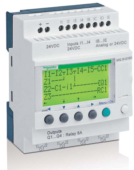
Start the training early
This is the generation that was born with cell phones and computers; put them to work in the reality they live in. Today’s electrical apprentice can be trained on this powerful equipment and go back on the job with valuable integration skills that can be applied to equipment that is available at local electrical suppliers. Some great applications of smart relays are irrigation systems, pump houses, HVAC, small scale machines, access control, lighting controls, motor control systems, solar tracking, astronomical timing, batch counting and alarm message systems.
Assigning actual control scenarios
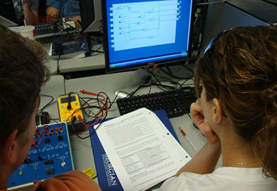
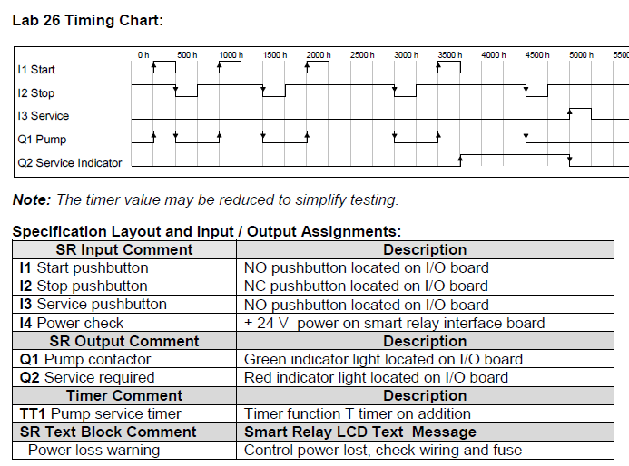
At the Georgian College Skilled Trades Centre, the instructors are well aware of the need for improved skills in installing the latest technology. Getting familiar with the equipment, reading the specification sheet and manufacturer’s instructions are all part of the program. A lot of equipment is usually accompanied with IEC drawings, timing charts and very specific installation instructions. We design our working projects and labs to meet situations that the apprentice will encounter; the argument “I will never see this” or “we don’t do this kind of work” doesn’t stand with the Instructors.
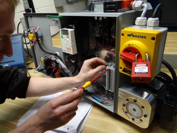
Variable frequency drives
Over a career, it is more likely than not an electrician will be involved in the installation of a VFD. It could be a small controller for a ventilation fan or a 500 Hp unit that drives a crusher motor. Regardless of the VFD size, in most cases the motor control and application functions available are the same. The powerful control functions available in micro drives and high power drives are delivered by a microprocessor and software that drives output transistors.
The physical size of the drive is determined by the power components in the front section, mid section and the output inverter section. Magnetic starters, SCR softstarters, single phase motors and controls for the most part will be become legacy devices. The inverter motor controller allows the highly efficient control of three phase motors, regardles of the supply type. As with other newer technology, the modern day apprentice must start learning early on this equipment.
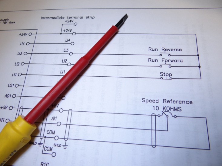
VFD instillation
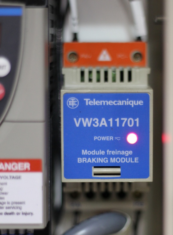
Drive manufacturers supply guidelines for the installation of the drive and ancillary equipment. Short circuit ratings and fuse requirements are usually specified. I stress the importance of reading the installation and set-up manual for the equipment. Fuse types such as HSJ are often specified and the electrical apprentice needs to be aware of this. Braking resistors, line and load reactors, and K-rated transformers are all covered in the drive training program. Most electricians can install line power and motor output wiring to a drive; the tricky part is setting up the drive to perform efficiently and meet very specific control requirements. This is where extensive VFD training comes into the spotlight.
VFD set-up, diagnostics and maintenance
As with automobile mechanics, the service electrician of today has experienced a change in the way equipment failures are diagnosed. The mechanic can no longer open the hood and change points or make adjustments to the carburetor.
The difference between the two trades is that when a VFD is installed it needs to be set up and programmed, and when a VFD fault occurs a diagnostic code will appear on the drive display. In the case of a fault code, today’s electrician will simply go online with a smart phone, find the user manual for the drive, and identify the fault code.
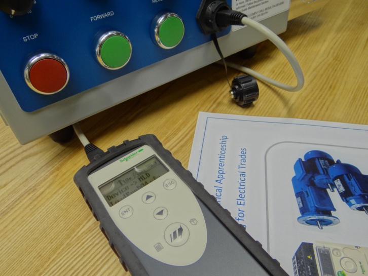
Today’s apprentice needs in-depth training in basic to advanced drive set-ups and troubleshooting. Setting up control types such as pump and fan, volts per hertz or sensorless vector can make a huge difference in the performance and energy savings of an installation. Adjusting the IR compensation levels for motor performance at low frequencies, motor auto-tuning, and acceleration and deceleration limits are all parameters that can be set as easily as saving a contact in a cell phone, but often get missed because of lack of training. As with smart relays, the apprentice needs exposure to IEC and NEMA drive drawings and also needs to make connections and program for an actual application.
As a skilled trades instructor at Georgian College, I like to round out the training by inserting common faults into VFD set-ups. This fault insertion technique allows the electrical apprentice to experience VFD troubleshooting first hand. In our programs, VFD maintenance is stressed; cleaning heat sinks and fans, retightening wiring connections and reforming capacitors are important for an apprentice to know.
This article first appeared in Dialogue Magazine, published by the Ontario Electrical League, http://www.oel.org
Norman Burton, M.E. C&M, Electrician Inter-Provincial, is General Manager of Burton Electro Technical Inc. H: 705 534 1993; C 705 529 9402; www.burtonelectrotechnical.com.


