L’implantation de solutions pour diminuer les arcs électriques dans les installations industrielles : 1re partie

Au cours des années passées, les installations industrielles situées partout dans le monde ont appris à reconnaitre l’importance d’identifier et de comprendre, ainsi que de mesurer et d’atténuer l’impact des risques associés aux arcs électriques dans leurs installations. Malgré le fait que de telles blessures ne sont pas fréquemment rapportées, leurs coûts très élevés font en sorte qu’elles représentent la catégorie de lésions la plus importante dans le milieu de travail industriel. L’étude de cas suivante met en scène une entreprise ayant de nombreux emplacements et opérant sur 13 usines au Canada et aux États-Unis, et comprend 6 leçons apprises.
This article examines the plans and processes reviewed and considered, the strategy deployed to manage/reduce arc flash hazards, and then discuss lessons learned in the implementation of new systems to improve electrical workplace safety.
Over the course of the past several years, industrial manufacturing facilities across the globe have learned to recognize the importance of identifying and understanding, measuring and mitigating the impact of arc flash hazards in their facilities. Although reported injuries are infrequent, the very high costs associated with these injuries make them one of the most important categories of injuries in the industrial workplace. In one utility, electrical injuries represented less than 2% of all accidents, but 28%–52% of injury costs. Immediate direct costs of arc flash incidents may be moderate, but these costs increase significantly over time. Coupling long-term direct costs with staggering indirect costs can raise the total cost of one incident to millions of dollars. The reason: an arc flash event is effectively an explosion, involving molten copper and extreme temperatures. The human impact result is often severe burn injuries and irreparable bodily injury, which drives medical and legal costs to very high levels. The hazards are so great, although certainly persons will always be in the proximity of energized equipment, there are really few if any reasons where energized work can be justified.
In considering standards focused on electrical workplace safety, it is important to recognize that current consensus documents are country based.
• In Canada, the Canadian Standards Association CSA
• In the U.S., the installation standard for electrical equipment is the National Fire Protection Association NFPA 70 National Electrical Code [2]. Article 110.16 of this standard entitled “Flash Protection” refers to the electrical workplace safety standard NFPA 70E-2012 Standard for Electrical Safety in the Workplace [3]
CSA Z462-12 is fully harmonized with the U.S. NFPA 70E-2012. Both the NFPA 70E-2012 and CSA Z462-12 mandates required safety practices for personnel working on or near energized electrical equipment. They determine the circumstances in which workers should wear specific personal protective equipment (PPE) clothing to protect them from the dangers posed by electrical arcs. One global standard focused on arc flash is IEEE Standard 1584-2002: Guide for Performing Arc Flash Hazard Calculations [4]. This standard presents methods for the calculation of arc flash incident energy (the heat energy defined in cal/cm2) and arc flash boundaries. Because this is treated as a global standard, IEEE 1584-2002 is being used by several multi-site industrial manufacturing companies that operate facilities in many countries. The IEEE 1584-2002 offers a process to quantify the heat energy exposure at any electrical point in an industrial system, thereby defining the proper PPE necessary before performing energized work. The standard does not however define workplace safety procedures such as lockout-tagout and energized work permits that are traditionally included in workplace safety standards.
As mentioned previously, because there is a significant risk to workers in performing energized work, the author’s recommendation is to find a way to turn the power off rather than take the chance of initiating an arc flash event. This said, there are some industrial users, particularly in process industries that elect to perform tasks such as troubleshooting and testing while electrical equipment is energized. This paper identifies case studies of select industrial facilities that have implemented site arc flash safety programs, highlighting the experiences of each as they worked to bring their respective sites into compliance with arc flash safety standards. In every case, the author’s employer was involved in working with the respective industrial client, with first-hand knowledge of the project experience.
Case study: multi-site cement processing manufacturer
This case study involves a multi-site cement processing business operating 13 cement plants in Canada and the U.S. The case study is detailed in a recent technical paper [5] that outlines details of a project to implement arc flash compliance to local standards across an enterprise. The cement producer operates globally and is one of the world’s leading producers in the cement industry, but this arc flash compliance project was limited to the company’s North American operations. For this project, IEEE Standard 1584-2002 was used as the tool to calculate the heat energy and both NFPA 70E-2012 Standard for Electrical Safety in the Workplace and CSA Z462-12 Workplace Electrical Safety were used as workplace safety guidelines for facilities in the U.S. and Canada respectively.
At the onset of project implementation, the cement producer engaged a global engineering services provider to perform site services and engineering studies. The services provider was chosen based on their extensive experience in the cement industry and a large and experienced team of over 100 power systems engineers, located at the company headquarters and also in field offices with both field engineering technicians and also power systems engineers across both Canada and the U.S. To perform the arc flash hazard analysis, data needed to be collected at each site including an accurate existing state “map” of all electrical power systems.
Then, the complete data package was sent to the centralized group of power systems engineers who updated the short-circuit and coordination studies and then completed a new arc flash study for each site. The starting point for collecting data was the existing plant single line drawing, along with recording of conductor lengths and protective device settings to verify that site documentation was correct. The utility serving each plant was also to be contacted for system information including the minimum and maximum fault currents that can be expected at the service entrance point of each facility. Although field service technicians were available and in close proximity to the 13 plant sites, the cement producer project team elected to deploy power systems engineers for the site work in collecting data. Their experience in performing power systems studies ensured that the information needed to complete the studies was collected on the first site visit, eliminating the need for multiple return trips. A centralized power systems engineering group led by a project engineer was deployed to support the systems studies effort following the data collection phase. This group was intentionally selected to be only a few people at the same location, which assured that the study methodology used and the resulting reports would be consistent across all of 13 plant sites.
Once the flash hazard analysis was performed, the calculated arc flash energy analysis yielded a PPE requirement for persons working on or near each energized electrical panel across each facility. Typically, the higher levels of PPE are required at the main cubicle of a 480 V unit substation and for some medium voltage systems. Because an arc flash event is generally limited to systems where bus voltage exceeds 240 V, the system model accounted for system busses only at 480 V and above.
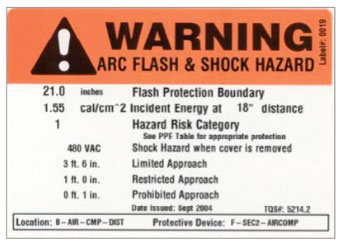
The study results included an Arc Flash & Shock Hazard label at each electrical panel as shown in Figure 1. Note the label quantifies the hazard in calories per centimetre squared (cal/cm2) at a working distance of 18 inches (about 500 centimetres). The label also identifies a Flash Protection Boundary of 21 inches. This is a distance where only “qualified persons” with appropriate PPE can safely be working while the panel is energized. PPE required while performing energized work in the panel must be rated above the 1.55 cal/cm2 hazard.

Figure 1: Typical equipment label designating arc flash in cal/cm2 and shock hazard along with Flash Protection Boundary and PPE.
After completion of all arc flash studies, each site received a detailed report that identified the electrical hazard at every panel in the system. Figure 2 shows a table of results from one of the plant studies.

Figure 2: The completed arc flash hazard study results were a table identifying each bus and the corresponding calculated incident energy based on formulas from IEEE Standard 1584-2002.
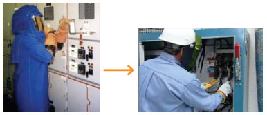
From this, note that the first bus identified as 416MCC-50/51-51G is a 4.16 kV motor control centre and the calculated incident energy is 4.1 cal/cm2. This is listed as a Hazard Risk Category, HRC #2. The second highlighted bus identified as FDR #3 SQD PNL is a 600 V motor control centre with calculated incident energy of 75.8 cal/cm2. The HRC for this panel is listed DANGER because PPE rated this high was not commercially available. In general, the unwieldy nature for PPE at the highest level comes with added risk (including loss of dexterity and heat exhaustion). Thus, the only alternative for this panel was to de-energize the system before performing work, or find a way to manage or engineer the incident energy level down. Following completion of the arc flash compliance project and posting of the labels identifying arc flash hazards at each panel, the individual cement manufacturing sites began to immediately focus on high incident areas of the plants, especially those that had historically required energized work. For these high arc flash hazard areas, the sites worked with the global services supplier to identify technologies that would allow the hazard to be managed to a lower level. The desire was to reduce the need for 40 cal/cm2 PPE to a more manageable level closer to 8 cal/cm2 as shown in Figure 3.

Figure 3: After the arc flash study is complete, facilities reviewed the results and identified areas where incident energy could be reduced, so workers can move from an unwieldy level of PPE (40 cal/cm2 shown at left), to a more manageable level of PPE (8 cal/cm2 shown at right).
In considering methods to reduce the arc flash incident energy at specific points of the electrical system, it is important to recognize that the heat reaching the skin of the worker is dependent primarily upon the
1. power of the arc at the arc location
2. distance of the worker from the arc
3. time duration of the arc exposure
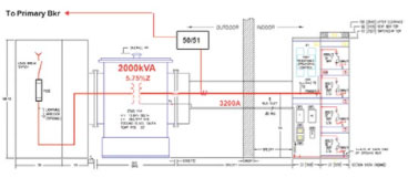
System modifications that impact these would result in a reduced arc flash hazard, ensuring in some cases that workers can perform energized work in lower levels of PPE. As one example, some of the unit substations included in the existing systems included an outdoor primary fused load-break switch, close coupled a substation transformer and then bus connected to indoor low voltage switchgear or motor control centres (see Figure 4).

Figure 4: Typical low voltage unit substation consisting of outdoor medium voltage switch/fuse and liquid-filled transformer, bus connected to indoor low voltage equipment. Addition of CTs and an overcurrent relay to trip an upstream breaker reduces the secondary arc flash hazard.
Local installation standards allow this configuration when the secondary bus is less than 10 metres. The secondary bus as shown for this substation configuration is not protected — the upstream protective device is the primary fuse! The arc flash energy on the low voltage bus is calculated at over 600 cal/cm2. One proposed solution to reduce arc flash energy is an added 50/51 overcurrent relay, including secondary bus current transformers at the substation transformer secondary throat. This added protective device offers secondary bus protection, sensing a fault condition should an arc flash event occur in the 480 V low voltage switchgear. If a fault occurs, the added
relay will sense the overcurrent and instigate a trip of an upstream medium voltage vacuum circuit breaker. With this proposed upgrade, workers performing testing or troubleshooting at the low voltage switchgear, or racking one of the low voltage power circuit breakers from the main bus, would be exposed to a much lower heat energy should an arc flash event occur. Adding an overcurrent protective relay that includes zone selective interlocking and/or a maintenance switch [6] that is engaged when the power circuit breakers are being connected or removed from the main bus would further reduce the hazard and required PPE.
One important point regarding this case study is that the arc flash hazard compliance project was implemented for existing facilities. In this case, legacy electrical switchgear and motor control centres has been in service for perhaps 10 to 40 years. Although some of the newer power distribution assemblies include upgraded features such as arc-resistant or internal arc testing, replacing the existing infrastructure was not practical. Virtually all of the system upgrades proposed to reduce arc flash hazards were retrofit in nature. The producer was challenged to find a way to enhance facility electrical workplace safety based on modifying or upgrading existing electrical equipment.
6 lessons learned
Overall, implementation of the arc flash compliance program for this multi-site cement producer was a tremendous success. Details outlining the project are included in the referenced technical paper [5] so they are not duplicated here. Overall, the success can be attributed to
• Assurance of buy-in at all levels via early engagement with company corporate and plant site leadership through developing and issuing an Arc Flash Criteria document nearly two years in advance of project execution
• Execution of the project only after a well-developed project scope document was established and circulated
• Setting clear expectations of the plant sites and the global services provider on schedule and costs of the project
• Selecting a service provider with the appropriate scale with the needed local presence to efficiently execute to meet the project schedule
• Aligning with a supplier with capabilities both in engineering services and product technologies available to assist in “managing” the arc flash hazard down for critical plant systems
• Leveraging scale across the enterprise and driving standards for data collection, studies, reports, labels and also site safety training to ensure quality and consistency
This case study is one of four published online by Eaton and has been lightly edited by EIN. Watch for more case studies in future issues.
Read the original: http://www.eaton.com/ecm/groups/public/@pub/@eaton/@corp/documents/content/pct_1562591.pdf.
References
[1] Canadian Standards Association CSA Z462: Workplace Electrical Safety, 2012 Edition
[2] NFPA70 National Electrical Code, 2012 Edition
[3] NFPA 70E: Standard for Electrical Safety in the Workplace. 2012 Edition
[4] IEEE Standard 1584: Guide for Performing Arc Flash Hazard Calculations. 2002 Edition
[5] G.M. Kemper, W.S Vilcheck, D.B. Durocher “The Journey of an Enterprise in a Process Industry Toward Improved Electrical Workplace Safety”, Conference Record IEEE IAS/PCA Cement Conference, April 2013
[6] C.G. Walker, “Arc Flash Energy Reduction Techniques Zone Selective Interlocking & Energy-Reducing Maintenance Switching”, Conference Record, 2011 IEEE IAS PPIC, Pgs 42-54


