Guide du Code, Partie 1 – 3
Souvent, les utilisateurs du Code se retrouvent dans des situations où certains règlements peuvent leur sembler étranges. Ces situations se présentent autant chez les concepteurs, les consultants, les installateurs, les inspecteurs, les étudiants, les formateurs que chez les experts qui développent les normes, et sont souvent liées au fait que le règlement a été mal identifié ou mal interprété. Il n’est peut-être pas celui requis par la tâche à effectuer. Le Code est un document complet et détaillé et la réponse ne se trouve pas toujours facilement. Voici un guide qui au cours des prochains mois vous aidera à trouver votre chemin dans le Code. Cettesemaine, la Section 4.
The CE Code is a comprehensive document. Sometimes it can seem quite daunting to quickly find the information you need. This series of articles provides a guide to help users find their way through this critical document. In this article: Section 4. It is not intended to replace the notes in Appendix B or the explanations of individual requirements contained in the CEC Handbook, but will hopefully provide some help in navigating the code.
Section 4 – Conductors
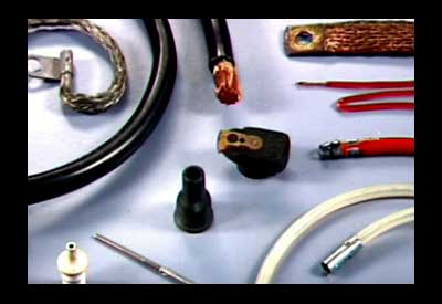
The definition of Conductor, from Section 0, isa wire or cable, or other form of metal, installed for the purpose of conveying electric current from one piece of electrical equipment to another or to ground.
Section 4 deals with the selection of type, ampacity and installation conditions of insulated conductors. It is a general section and therefore it applies to all conductors supplying lighting, appliances and power circuits. The selection of other conductors, such as for control, grounding, emergency, safety, fire alarms, airport installations, renewable energy, communications, cathodic protection, and others, will be governed by individual sections covering these situations. Individual sections may also apply as general sections, or may have rules that reference or amend Section 4. For example, Sections
• 6—Services and service equipment
• 8 —Circuit loading and demand factors
• 10—Grounding and bonding
• 12 —Wiring methods
• 14 —Protection and control
• 16 —Class I and Class II circuits
• 26 —Installation of electrical equipment
For this reason it is important to compare the rules in Section 4 with the rules governing conductors in the section dealing with your particular installation. For instance, Rule 4-002 requires that the minimum size for all copper conductors, except for flexible cord, equipment wire, or control circuit wire, and cable (which are specifically covered by other sections) is No.14 AWG and No. 12 AWG if aluminum. However, in Section 6, Rule 6-302 Installation of overhead consumer’s service conductors requires that the minimum size for overhead consumer’s service conductors is No.10 AWG copper or No. 8 AWG aluminum. Even though there are amendatory sections and rules later in the code, it is still important that you refer to Section 4 first when selecting and installing any conductor.
Conductor selection factors
When selecting a conductor there are a number of factors to be considered. Because of the complexity of conditions, you need to have a process to determine the correct type and size for your application. The first consideration is to choose the size of conductor you need based on the
• current it will be required to carry
• conditions under which it will be installed
• type of conductor or cable to be used
Rule 4-004 Ampacity of wires and cables contains 7 items each in subrules (1) and (2) covering scenario options each for copper and aluminum that need to be studied and chosen. In addition, there are 21 other factors in the subsequent subrules to be considered.
Although this may seem daunting at first, it is simply a matter of going through the list of options and conditions and choosing the ones that apply to your situation. Rule 4-004 will then direct you to the correct table and correction factor for your situation.In some cases you will be directed to use the IEEE 385 calculation method or the tabulated information tables in Appendix D. The IEEE 385 Standard Power Cable Ampacity Tables contains all pertinent equations and has the electrical/thermal analog circuit and calculation examples in the annex.
Once the right ampacity has been chosen or calculated, the next factor to consider, according to Rule 4-006, is the temperature limitations on the conductor ampacity you have chosen. Where the maximum conductor termination temperature is marked on the equipment, you will have already chosen the minimum size of conductor based on the correct temperature column of tables 1, 2, 3 or 4. Where the maximum conductor termination temperature is not marked on the equipment, the temperature to be used is: 600 C for equipment rated 100 A or less or marked for use with No.1 AWG or smaller conductors, or 750 C for equipment rated more than 100 A or marked for use with conductors larger than No. 1 AWG.
These conditions apply only to the first 1.2 meters of conductor length measured from the termination point of the equipment. One other condition to note when using a single conductor cable with a metal sheath or armour: induced voltages may cause the conductor insulation temperature to exceed its rating. In this case, Rule 4-010 Induced voltages and currents in metal armour or sheaths of single-conductor cables requires you to derate the conductor along with some other procedures to mitigate this situation.
The next important consideration outlined in Rules 4-008, 4-012, 4-014, 4-016, 4-018, 4-020, 4-040 and 4-042 is the selection of the type of insulated conductor, flexible cord, equipment wire or portable power cable. In some cases these rules will specify minimum sizes and ampacities for the various types.
Finally we go back to Rules 4-022, 4-024, 4-026, 4-028, 4-030, 4-032, 4-034, and 4-036, which provide for the use of a common neutral, installation, identification and use of neutral and identified conductors. Rule 4-038 Colour of conductorscovers the colouring of insulated grounding and bonding conductors, and where colour-coded circuits are required.
You will note that Section 4does not apply to non-insulated grounding or bonding conductors. The use, size andampacity of these conductors are covered by Section 10, which we will deal with in subsequent instalments.
In the next installment we will explore Section 6 — Services and service equipment.
The source for this series of articles is the Canadian Electrical Code, Part I, published by CSA
Pour lire les articles précédents de la série:
– Guide du Code, Partie 1 – 10
William (Bill) Burr est l’ancien président du Canadian Advisory Council on Electrical Safety (CACES), et l’ancien directeur de l’Electrical and Elevator Safety pour la province de la Colombie-Britannique. Il a aussi été directeur de l’Electrical and Gas Standards Development et directeur du Conformity Assessment pour le Groupe CSA. Bill peut être rejoint à Burr and Associates Consulting au billburr@gmail.com.


